Force of dressing grinding wheels by diamond rollers with orderly arrangement grains
-
摘要: 为提升滚轮的修整性能和使用寿命,明确滚轮表面磨粒的不同排布对其修整性能的影响,采用错位、阵列和叶序3种磨粒排布的金刚石滚轮修整砂轮,对修整过程进行有限元仿真,并设计修整实验验证仿真结果。结果表明:在金刚石滚轮修整砂轮的过程中,磨粒的有序排布会对修整力产生影响,其中阵列排布的滚轮修整力最大,错位排布次之,叶序排布最小;叶序排布相较于错位与阵列排布,有利于减少滚轮表面磨粒磨损,提升滚轮的修整性能与使用寿命。Abstract:
Objectives With the increasing improvement of science and technology and industrial levels, the modern manufacturing industry has higher and higher precision requirements for grinding processing, and the grinding quality can be improved by enhancing the ability of diamond dressing rollers. However, the current research on the grinding dressing process is mostly based on experiments. Since grinding is a high-speed and complex machining process, the dressing experimental cost of diamond rollers is higher. Therefore, this paper explores the influence of surface diamond grain arrangement on the dressing ability of diamond rollers through finite element simulation, and designs experiments to verify the reliability of the simulation results. Methods The finite element analysis software Abaqus is used to carry out kinematic simulation of the dressing grinding process of the roller. First of all, in order to simulate the randomness of the real abrasive grain shape, the sphere method of plane-cutting cubes is used to obtain a more realistic abrasive grain model. Algorithms are designed for the coordinates of abrasive grains in three types of arrangement: array, misalignment, and leaf sequence, to achieve the accurate arrangement of abrasive grains on the surface of the roller model. The Johnson-Holmquist-2 (JH-2) intrinsic parameters model of 99.5% alumina ceramics is used to approximately characterize the damage evolution of white corundum grinding wheels during dressing. To verify the accuracy of the results obtained through this simulation method, dressing experiments are set up to form a control with the simulation group. Results Taking the dressing force generated in the dressing process as the evaluation index, the simulation and experimental results are analyzed: (1) A comparative analysis of the data obtained from the simulation is carried out, and it is found that diamond wheels with surface abrasive grains arranged in an array manner would generate a larger dressing force during the dressing process, followed by the staggered-arrangement wheels, and the diamond wheels with a leaf-sequence arrangement would have the smallest dressing force. In other words, the arrangement of abrasive grains on the surface of the diamond dressing wheel affects the dressing force. (2) The dressing force results obtained from the experiments also show that under these three arrangements, the dressing force generated by the array roller is the largest, and the dressing force generated by the leaf sequence is the smallest. (3) Comparing the dressing force data obtained from the simulation and experiment, it can be seen that the fluctuation of the dressing force obtained from the experiment is smaller than that of the simulation. The maximum error of both normal dressing force is 12.87%, and the maximum error of tangential dressing force is 17.16%. Conclusions (1) Comparing the dressing force results of the simulation and experiment, it is found that the fluctuation of the experimental data is smaller than that of the simulation results. This is due to the fact that the abrasive grains in the simulation are generated randomly. Even if two neighboring abrasive grains differ in parameters such as protruding height, effective action area, and the angle of abrasive grains' vertices, the fluctuation of the dressing force is still larger under the state of smooth grinding. The diamond rollers used in the experiments have undergone surface reshaping treatment, and the parameters such as the emergence height and vertex angle of the abrasive grains on the surface are more consistent with the simulation model. As a result, the fluctuation of the dressing force is smaller and smoother. The dressing force measured in the experiment is smaller compared with the simulation, which indicates that the dressing roller can be shaped to make the dressing process smoother and improve its dressing ability. (2) The reason for the difference in dressing force of diamond wheels with different arrangements of abrasive grains: Under the condition of the same concentration of abrasive grains on the surface, the abrasive grains of the roller with an array arrangement result in fewer effective abrasive grains due to a large number of overlapping grinding trajectories. In contrast, the leaf-sequence arrangement has the unique characteristic where each abrasive grain is located on a circumference that is different from that of any other abrasive grain. Therefore, the trajectory lines of each abrasive grain on it do not overlap, resulting in the largest number of effective abrasive grains and the smallest dressing force. (3) The similarity between the simulation and the dressing force obtained from the experiment verifies the reliability of the simulation of the dressing process of the wheel by finite element analysis. It also proves the feasibility of replacing the material properties of the white corundum grinding wheel with the JH-2 intrinsic parameter of alumina ceramics with 99.5% content in the kinetic simulation. -
Key words:
- diamond /
- orderly arrangement /
- grinding /
- dressing /
- phyllotactic pattern
-
金刚石滚轮主要由金刚石磨粒、结合剂与金属基体组成,是一种主要应用于成型砂轮修整的高精密超硬金刚石刀具,具有较高的修整效率和加工精度,能够保证加工尺寸的一致性。目前,工业上制造的金刚石滚轮,其表面磨粒多为无序排布,而已有研究表明,磨具表面磨粒有序排布具有优于无序排布的磨削性能。
李瑞昊等[1]提出了一种曲面砂轮表面磨粒优化排布的设计方法,并验证了磨粒有序排布的砂轮磨削时产生的磨削力相较于无序排布的砂轮要更小,磨粒磨损程度也更小。YUAN等[2]使砂轮磨粒群实现规则排布,并使用该砂轮磨削碳纤维复合材料,获得了较低的工件表面粗糙度。ZHANG等[3]制造了按金刚石晶须方向排布的新型砂轮,该砂轮通过增大容屑空间来得到较好的工件表面质量。国外也进行了相当多的研究与验证,如KOSHY等[4]开展了有序排布磨粒砂轮表面的磨粒排布间距和排布高度对表面粗糙度的影响的研究,结果表明,磨粒错位排布的砂轮能够有效改善磨削表面的粗糙度;美国和日本的NORITAKE公司在研制用于精密磨削加工的单层焊金刚石磨轮时采用了金刚石有序排列技术,实验表明,其磨削后的工件表面粗糙度得到明显改善[5]。
在磨粒的多种有序排布方式中,关于错位、阵列和叶序的研究最多。车东泽等[6]以工程化砂轮加工的结构化凹坑为基础,探究得出相同数目的磨粒叶序、阵列、错位排布砂轮中,叶序排布砂轮磨削工件表面的凹坑空间利用率最大。赵国伟等[7]建立了错位、阵列和叶序3种排布砂轮的数学模型,利用Matlab进行仿真,得出叶序排布砂轮获得的工件表面粗糙度值低于其他排布方式的结论。陈晨等[8]通过叶序、错位和无序3种排布的砂轮磨削TC4,得出在相同磨削条件下,磨料有序化能有效降低TC4磨削温度、获得更低工件表面温度的结论。
目前,该方面研究多集中于砂轮表面磨粒的不同排布对加工工件的影响,而缺乏针对滚轮表面磨粒的不同排布对其修整能力的影响的研究。金刚石滚轮作为广泛应用的成型砂轮修整工具,其制造成本较高,且金刚石磨粒在修整过程中易发生磨损,会降低滚轮的修整性能,磨粒损耗的程度也决定了滚轮的使用寿命。因此,探讨滚轮表面的磨粒排布对其修整性能以及使用寿命的影响具有实际意义。滚轮对砂轮的成型修整可以视作外圆磨削,在外圆磨削加工过程中影响加工质量的参数较多,其中磨削力是影响磨削温度、磨削功率、磨料磨损及工件表面磨削质量等的重要因素[9]。主要体现为较大的磨削力会使滚轮表面的磨粒损耗更快[1],缩短金刚石滚轮的使用寿命,增加修整成本。同时,更少的有效磨削刃在增加修整过程磨削热的同时会减少磨削区域的容屑空间,从而影响磨屑及磨削液的流动,进而不利于热量散发,导致磨削区域温度升高[9],影响修整质量与效率。
本文以轴承内圈沟道磨削砂轮成型修整为研究主体,通过对错位、阵列以及叶序3种磨粒排布的金刚石滚轮修整砂轮的过程进行有限元仿真来研究磨粒排布对成型修整过程中修整力的影响,并设计错位排布滚轮修整实验验证仿真结果,以得到更加合适的排布方式,提升滚轮的修整性能及使用寿命。
1. 砂轮成型修整仿真
为降低实验成本并提高效率,本文通过Abaqus有限元分析软件对错位、阵列以及叶序3种磨粒排布的金刚石滚轮修整砂轮的过程进行动力学仿真。
1.1 几何模型构建
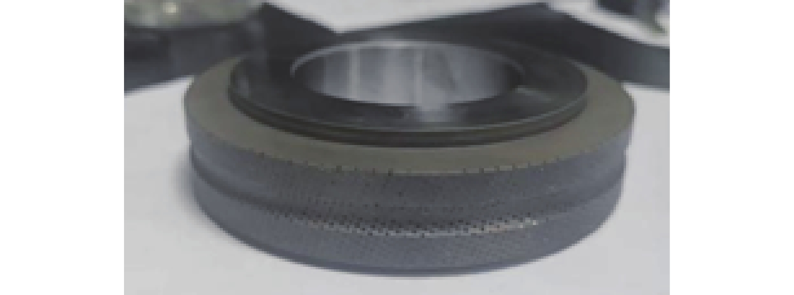
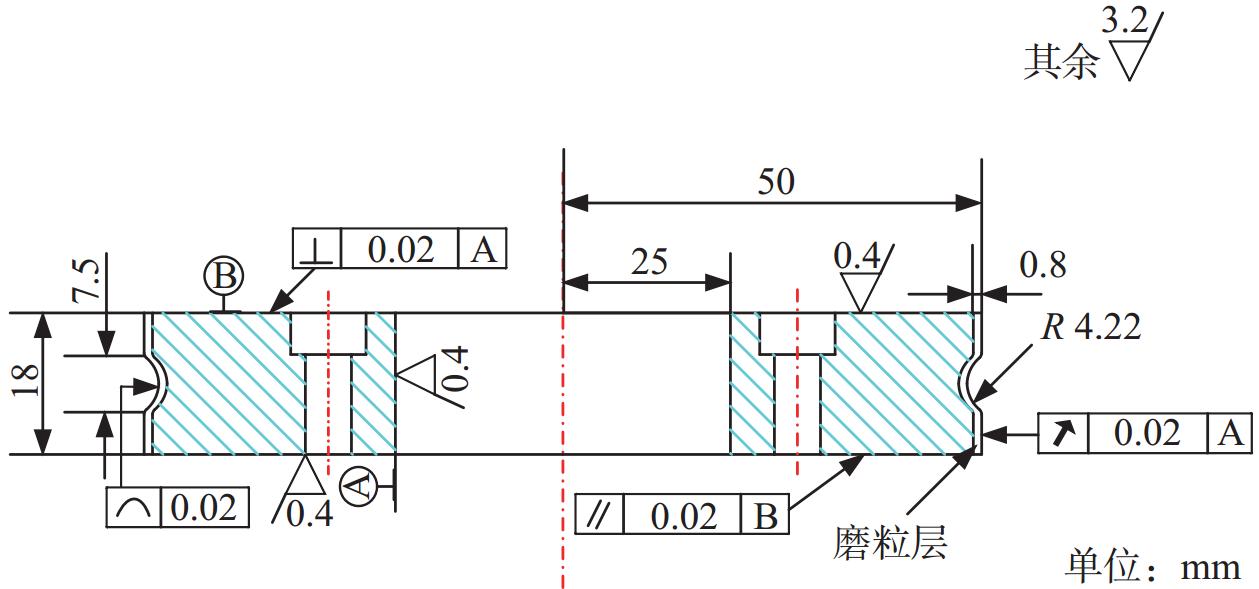
轴承内圈沟道磨削用金刚石修整滚轮如图1所示,其设计图纸如图2所示。该滚轮表面的金刚石磨粒粒度为16 / 18,表示该规格的磨粒落在筛孔尺寸是1 000 μm与1 180 μm的2层筛子之间[10],即金刚石颗粒直径上限为1 180 μm,下限为1 000 μm。
 图 1 轴承内圈沟道磨削用金刚石修整滚轮Figure 1. Diamond dressing roller for trench grinding of bearing inner ring
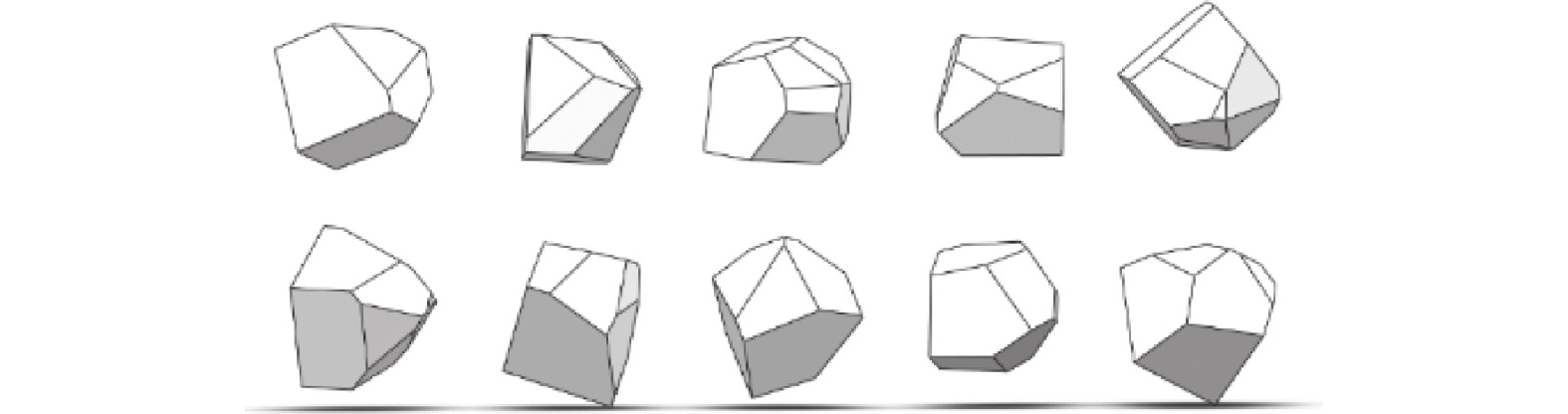
金刚石磨粒形状为不规则多面体,为与实际金刚石磨粒保持一致,本文仿真所用磨粒的建模方法为建立一个直径为1 000 μm(粒径最小值)的球体和边长为1 180 μm(粒径最大值)的立方体,使球心与立方体的体心重合,让球的多个随机切面切割该立方体,所得到的随机多面体即为磨粒模型[11]。
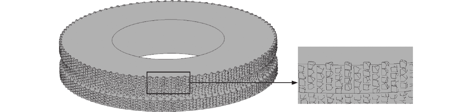
通过该方法生成的错位排列滚轮三维模型如图3所示,该模型包含1个基体和2 400个磨粒,其中磨粒均选自一个由800个不同形状的磨粒组成的磨粒库。磨粒库部分磨粒如图4所示。
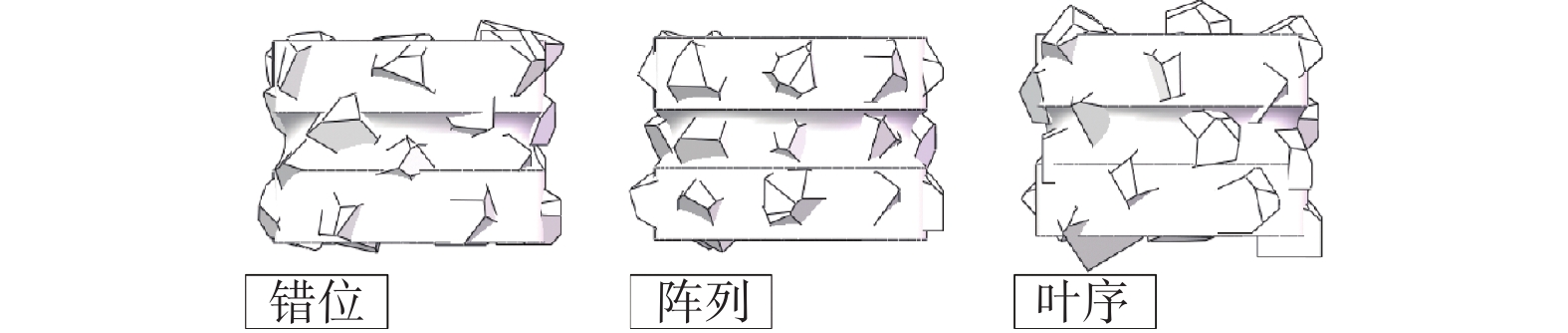
由于计算机的计算能力有限,为了提高仿真速度,将模型基体尺寸按比例缩小而保持磨粒尺寸不变,以通过减少磨粒数量达到降低仿真计算量的目的。最终选择的仿真模型参数如表1所示,该尺寸既可以较好地突出磨粒排布特点以区分阵列、错位和叶序排布,又减少了磨粒数量和仿真计算压力,创建的修整滚轮模型如图5所示。
表 1 滚轮与砂轮仿真模型参数Table 1. Parameters of roller and grinding wheel simulation model模型 外径 d1 / mm 孔径 d2 / mm 厚度 t / mm 金刚石滚轮 5 2.5 3.65 白刚玉砂轮 20 10 3.65  图 5 不同排布下金刚石修整滚轮模型Figure 5. Diamond dressing roller model under different arrangement
对叶序排布模型做如下简单介绍。Van Iterson模型[12]最早将植物中的叶序排布理论应用在磨粒排布中,该模型的主要参数为:
$$ \left\{\begin{array}{l}{\phi }_{i}=n\times \alpha \\ R=c\\ H=h\times n\end{array} \right.$$ (1) 式中:$ (\phi_i,R,H) $为第$ n $颗磨粒的圆柱坐标,n为磨粒在圆柱表面上的序数(从圆柱底部算起),$ \alpha $为叶序发散角(第n颗磨粒与第$ n + 1 $颗磨粒的夹角, $ \alpha $=137.508°),h为叶序生长系数(第n颗磨粒与第$ n + 1 $颗磨粒的高度差)。
由于砂轮表面的磨粒过小,而砂轮的规格远大于滚轮基体,砂轮表面的大量磨粒会严重影响仿真的计算速度。因此,在砂轮表面的磨粒分布随机且紧密,并且砂轮磨粒远小于滚轮表面金刚石磨粒的基础上,本文将砂轮的最外一层视为平整的磨粒层,即不再在模型中添加砂轮磨粒,以提高仿真效率。
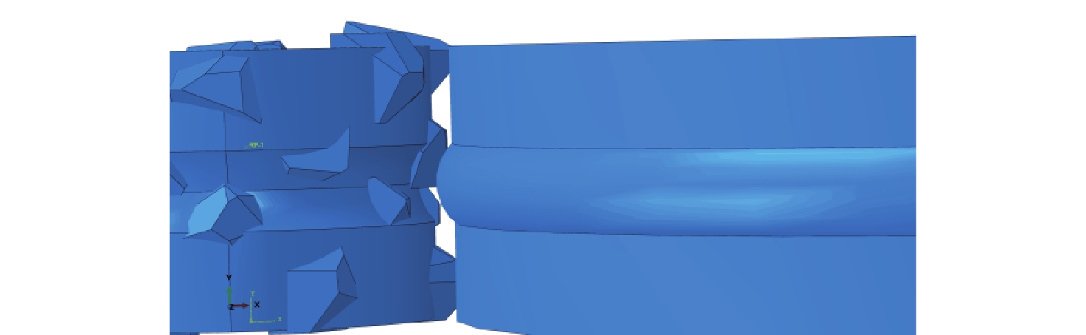
在装配好的修整模型中,滚轮与砂轮的接触弧区域模型如图6所示。滚轮表面磨粒的出露高度按照实际滚轮设置,为0.1~0.2 mm;通过控制分析时间来控制砂轮的进给长度 < 0.1 mm,从而确保砂轮与滚轮的修整始终为磨粒作用。
1.2 有限元仿真前处理
1.2.1 材料的性能参数
金刚石滚轮与白刚玉砂轮的材料参数如表2所示。
表 2 金刚石与白刚玉材料参数Table 2. Diamond and white corundum material parameters材料 密度 ρ /
(t·mm−3)杨氏模量 E / MPa 泊松比 v 金刚石 3.52 × 10⁻⁹ 1.05 × 10⁶ 0.1 白刚玉 3.98 × 10⁻⁹ 3.5 × 10⁵ 0.22 材料 热膨胀系数 $ \alpha $ 热导率 $ \lambda $ /
(W·m−1·K−1)比热容 c /
(mJ·t−1·K−1)金刚石 1.26 × 10⁻⁶ 2 000 4.2 × 10⁸ 白刚玉 30.145 6.0 × 10⁸ 1.2.2 材料本构模型的选择
1992年,Johnson-Holmquist(JH)本构模型首次被提出用于描述脆性材料对大变形的响应。该模型的第1版没有考虑材料的渐进损伤,同时材料强度的描述用代表性压力和损伤机制上的多个线性段表示。该模型的第2个版本,即JH-2解决了这些问题,将材料强度和损伤表示为代表变量的函数。更重要的是,JH-2模型考虑了材料内部损伤的演化。JH-2模型还包括通过Hugoniot Elastic Limit(HEL)对强度参数进行归一化,以便直接地比较各种材料。
JH-2本构模型包括以下3大模型。强度模型的标准化形式为:
$$ \begin{array}{l}\left\{\begin{array}{l}\sigma^*=\sigma_{\mathrm{i}}^*-D\left(\sigma_{\mathrm{i}}^*-\sigma_{\mathrm{f}}^*\right) \\ \sigma_{\mathrm{i}}^*=A\left(P^*+T^*\right)^N\left(1+C\mathrm{ln}\dot{\varepsilon}^*\right) \\ \sigma_{\mathrm{f}}^*=B\left(P^*\right)^M\left(1+C\mathrm{ln}\dot{\varepsilon}^*\right)\end{array}\right.\end{array} $$ (2) 式中:$ {\sigma }^{*} $为当前的归一化等效应力,$ D $为损伤变量($ 0\leqslant D\leqslant 1 $),由此参数确定强度模型中归一化等效应力组成部分,$ {\sigma }_{\mathrm{i}}^{*} $为材料完整强度,$ {\sigma }_{\mathrm{f}}^{*} $为材料断裂强度,$ A、B、C、M、N $为材料常数,$ P、T $分别为静水压力和最大静水拉伸强度,将其归一化处理可得到$ {P}^{*} $、$ {T}^{*} $,$ \dot{\varepsilon}^* $为归一化应变率。
在JH-2模型中,损伤是一个累积过程。损伤材料的归一化强度为:
$$ \left\{\begin{array}{l}D=\displaystyle\sum_{ }^{ }\dfrac{\Delta\varepsilon_{\mathrm{P}}}{\varepsilon_{\mathrm{\mathit{\mathrm{p}}}}^{\mathrm{f}}} \\ \varepsilon\mathrm{_{\mathrm{\mathit{\mathrm{P}}}}^{\mathrm{f}}}=D_1\left(P^*+T^*\right)^{D_2}\end{array}\right. $$ (3) 式中:$ \Delta\varepsilon_{\mathrm{P}} $为材料在一个时间步长的等效塑性应变增量,$ {D}_{1} $、$ {D}_{2} $为材料参数。如果$ {P}^{*}=-{T}^{*} $,则材料不能承受任何塑性应变。$ \varepsilon\mathrm{_p^f} $的值随$ {P}^{*} $的增大而增大。
整体性流体静力状态方程(当$ D=0 $时)为:
$$ \left\{\begin{array}{l}P=K_1\mu+K_2\mu^2+K_3\mu^3\ \ \ \mu\geqslant0 \\ P=K_1\mu\ \ \ \mu < 0 \\ \mu=\rho/\rho_0-1\end{array}\right. $$ (4) 式中:$ {K}_{1} $为体积模量,$ \mu $为体积应变,$ {K}_{2} $和$ {K}_{3} $为材料常数,其值可通过静压实验得到,$ \rho $为瞬时密度,$ {\rho }_{0} $为初始密度[13]。
白刚玉砂轮磨粒的主要成分为Al2O3,其质量分数在99%以上,此外还含有少量的Fe2O3、SiO2等。由于白刚玉砂轮的本构参数取决于其具体制造材料以及生产工艺,不易获得,因此使用Al2O3质量分数为99.5%的Al2O3陶瓷的JH-2本构模型来近似表征白刚玉砂轮对磨削载荷的响应,具体参数如表3所示。
本构
模型密度 ρ /
(t·mm− 3)剪切模量
G / MPaA N B M C 3.7 × 10− 9 90 160 0.93 0.6 0.31 0.6 0 $ \dot{\varepsilon}_0 $ 拉伸强度
Rm / MPa$ {\sigma }_{\mathrm{i}}^{\mathrm{m}\mathrm{a}\mathrm{x}} $ $ {\sigma }_{\mathrm{f}}^{\mathrm{m}\mathrm{a}\mathrm{x}} $ HEL /
MPa$ {p}_{\mathrm{H}\mathrm{E}\mathrm{L}} $ /
MPa$ \beta $ 1 200 1.004 4 0.2 279 0 1 460.0 1 $ {K}_{1} $ $ {K}_{2} $ $ {K}_{3} $ 130950 0 0 损伤
模型$ {D}_{1} $ $ {D}_{2} $ $ {\stackrel{-}{\varepsilon }}_{\mathrm{f},\mathrm{m}\mathrm{a}\mathrm{x}}^{\mathrm{p}\mathrm{l}} $ $ {\stackrel{-}{\varepsilon }}_{\mathrm{f},\mathrm{m}\mathrm{i}\mathrm{n}}^{\mathrm{p}\mathrm{l}} $ FS IDamage 0.005 1.0 0.005 0 0.2 0 1.2.3 网格划分
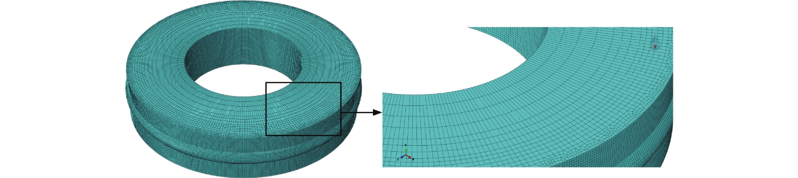
砂轮仿真磨削加工部分仅为最外圈一层,为使结果精确同时保证求解效率,对砂轮的网格进行部分加密。先将砂轮划分为4个区域,从接触面向非接触面网格逐渐由密到疏,共产生213 408个网格单元。部件网格使用六面体单元划分,划分好的砂轮网格模型如图7所示。
1.2.4 相互关系创建
由于金刚石磨粒的弹性模量与屈服强度远远大于白刚玉的,其在磨削过程中基本不发生形变,所以给滚轮整体施加刚体约束。对砂轮施加MPC约束,将其运动都耦合在一点上。将滚轮磨粒与砂轮最外圈部分创建表面与表面接触,类型为罚接触,摩擦系数为0.2。
1.2.5 载荷的施加
仿真时,滚轮与砂轮的线速度与磨削进给速度均与实验保持一致,按照实际生产中轴承内圈沟道成型修整的加工条件进行设置,滚轮线速度为0.424 m / s,砂轮线速度为31.164 m / s,磨削形式为逆磨,砂轮进给速度设置为0.002 33 mm / s。此外,在分析步模块进行质量缩放处理,以提高程序运算效率。为避免过量调整导致分析结果不准确,需要确保动能与内能的比例 < 5%。
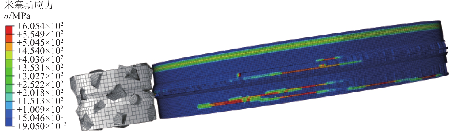
1.3 仿真结果与分析
错位排布的滚轮修整仿真应力云图如图8所示。
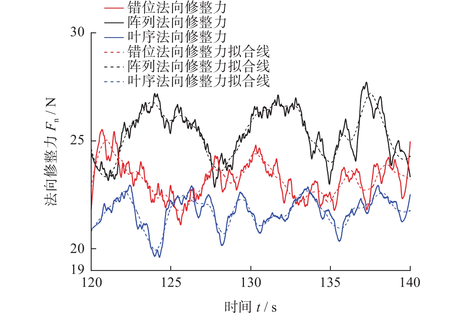
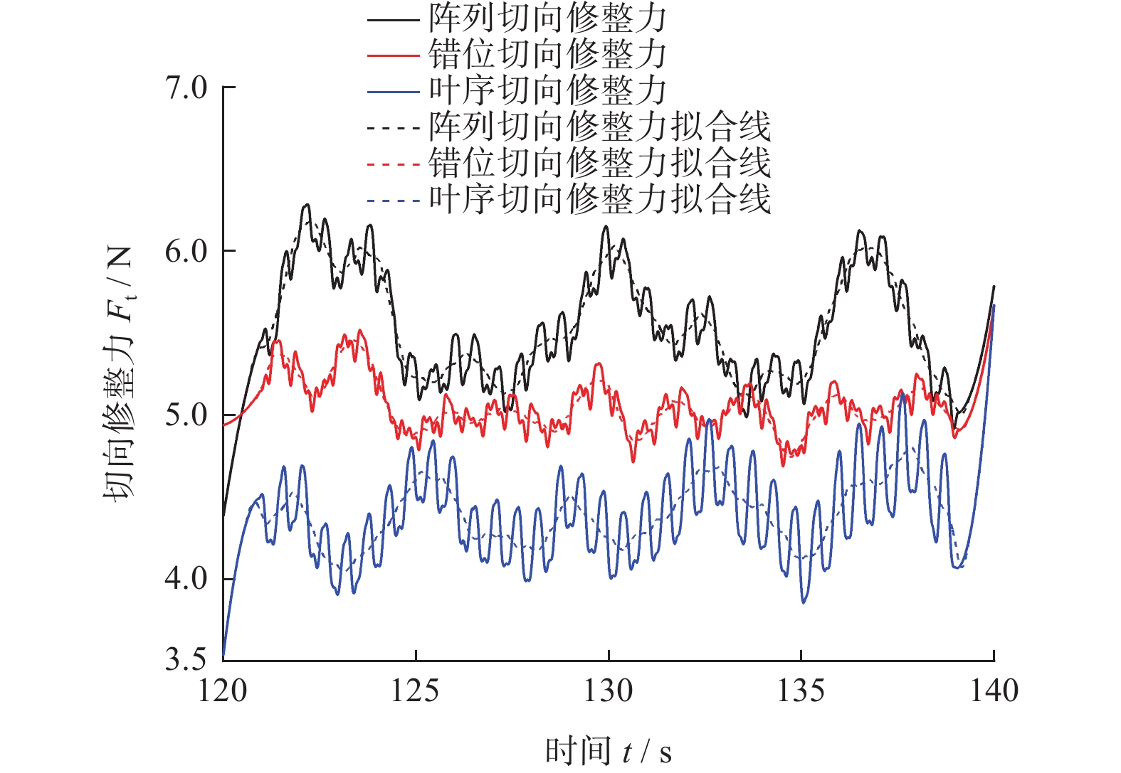
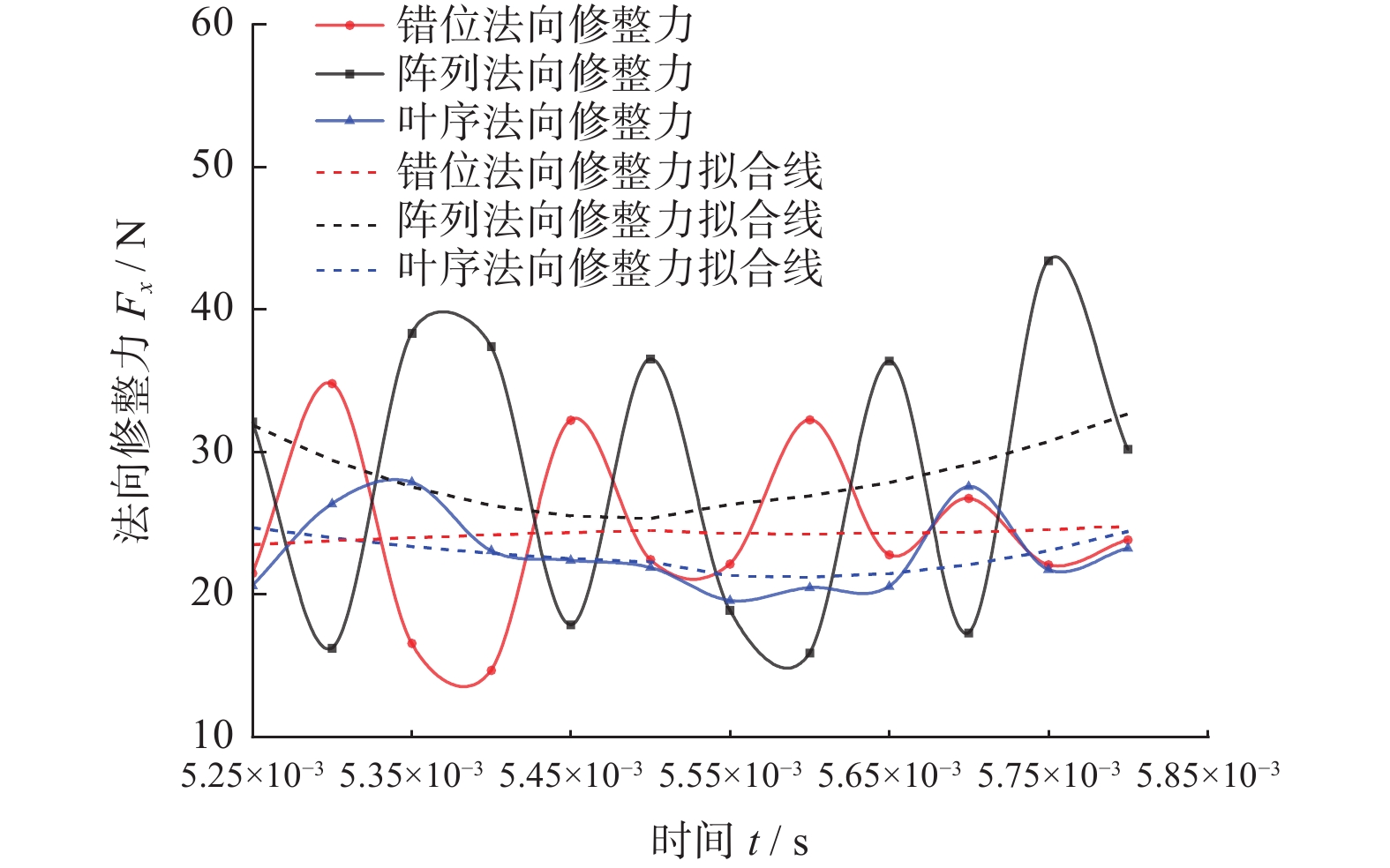
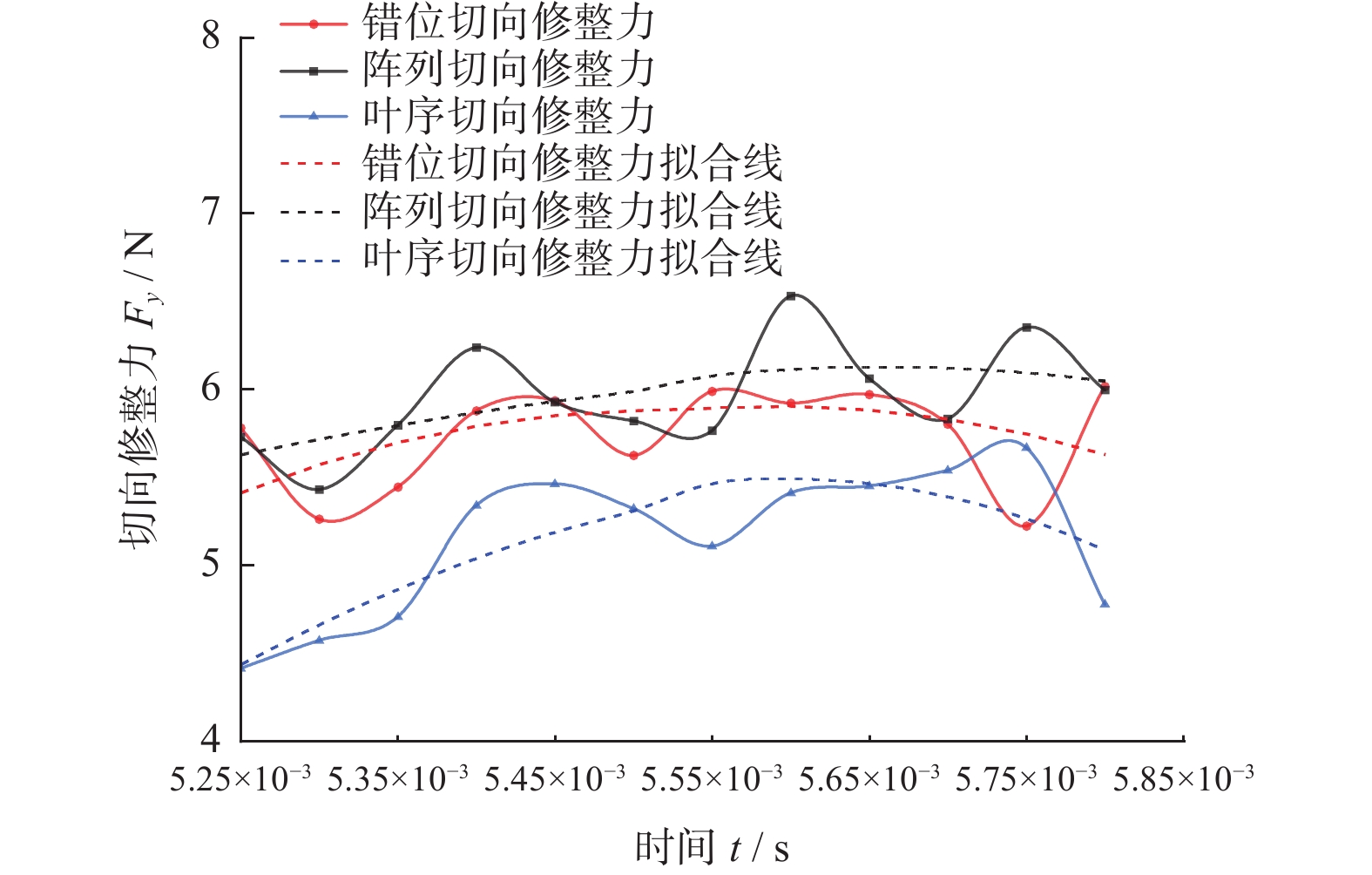
修整力可以分为法向修整力、切向修整力与轴向修整力3个互相垂直的力,由于成型磨削仅做纵向进给,其轴向修整力远小于法向与切向2个方向的修整力,甚至接近于0,因此对修整力的研究主要针对法向与切向。对错位、阵列和叶序3种磨粒排布的砂轮修整模型均按照上述设置进行仿真,提取砂轮中心参考点的修整力历程数据与实际滚轮宽度比例计算,取其平稳磨削阶段的数据进行曲线绘制,得到仿真修整力结果如图9和图10所示。
分析图9与图10,可以发现修整力的波动较大,这是由于修整力除了受到磨粒排布因素的影响外,还会受到磨粒出刃高度、有效作用面积以及顶点角等[15]众多因素的影响,而本研究中的磨粒均为随机生成,即2颗相邻磨粒在出刃高度、有效作用面积以及磨粒顶点角等参数上也存在差异,因此在平稳磨削状态下,其修整力波动值依然较大,不易直接观察。
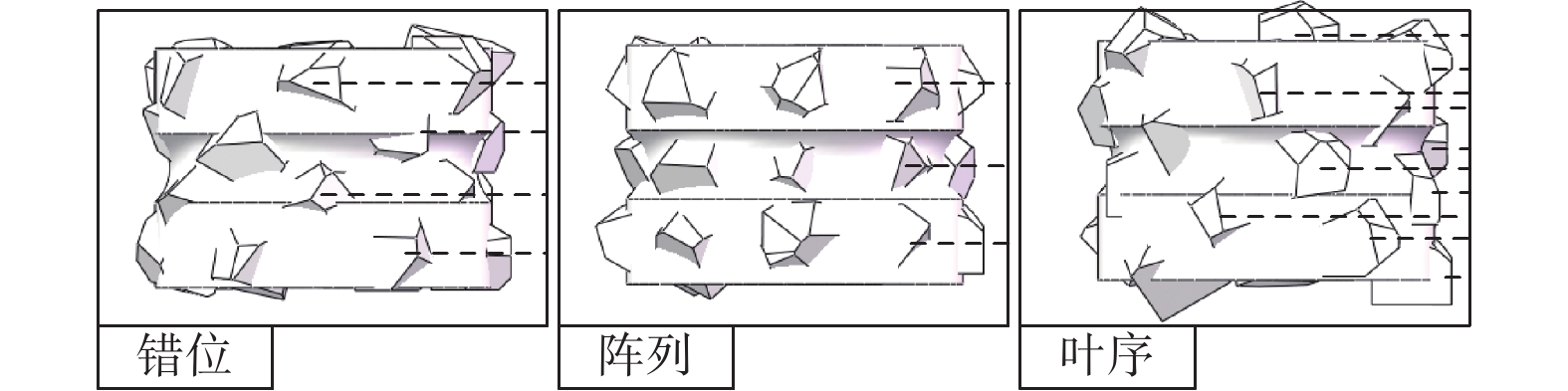
对各排布下的曲线进行拟合,由拟合线可以较直观地发现,滚轮表面的金刚石磨粒排布方式对其修整过程中的修整力存在一定影响,其中阵列排布的法向和切向修整力均为最大,错位排布次之,叶序排布的最小。这是因为阵列排布滚轮的轨迹仅有3条,其轨迹大量重合,导致有效磨粒数量较少,如图11所示,图中黑色虚线为磨粒轨迹;对错位排布来说,磨粒轨迹增加至4条,有效磨刃更多,修整力相较于阵列排布的更小;而对叶序排布而言,由于其特殊的排布性质,每个磨粒均位于不同于其他任何一个磨粒的圆周上,故其上24个磨粒会产生24条并不重合的轨迹线(图11中并未标示出所有轨迹线,仅作说明),所以其有效磨粒数量最多,修整力也最小。
 图 11 3种排布的金刚石滚轮模型磨粒轨迹线Figure 11. Three kinds of arrangement of diamond roller model abrasive grains track line
2. 错位排布滚轮修整实验
通过设计错位、阵列和叶序3种排布金刚石滚轮的磨削修整实验与仿真结果形成对照,验证仿真参数设置的准确性。
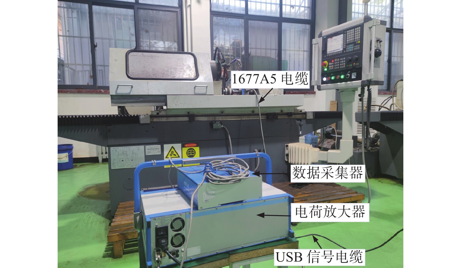
2.1 实验设备
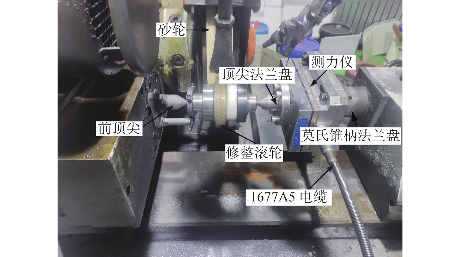
实验用到的外圆磨削测力系统由电荷放大器、数据采集系统以及测力仪传感器等组成。测力仪装置是由瑞士Kistler公司研发生产,型号为9257B的平板测力仪,其测力范围为−5~10 kN,精度在0.01 N。实验过程中,需要将其进行改装以与外圆磨床搭配使用,实现外圆磨削力的测量,具体方法为使用时将磨床后顶尖卸下,换上测力仪装置(改装后的顶尖法兰盘部分)以代替后顶尖检测外圆磨削力。外圆磨床为上海机床厂有限公司的数控外圆端面磨床MKE1620A,该磨床最大磨削直径为200 mm,最大磨削长度为500 mm,工件转速为68~432 r / min,砂轮转速为1 488 r / min。实验仪器或设备均满足实验要求。外圆磨削测力装置如图12和图13所示。
表 4 砂轮规格参数Table 4. Grinding wheel specification参数 取值 外径 d1 / mm 400 孔径 d2 / mm 203 厚度 t / mm 50 粒度 80 硬度 K 2.2 实验设计
修整实验开始前,先用金刚石笔修整砂轮表面,目的是使砂轮轮廓保持平整均匀,而后用滚轮对砂轮进行成型磨削,再用砂轮加工轴承钢试件模拟砂轮的正常磨削磨损,最后使用滚轮进行修整,采集该修整过程产生的修整力数据。实验设计参数如表5。
表 5 滚轮修整实验设计Table 5. Roller dressing test design阶段 滚轮转速
v1 / (r·min− 1)砂轮转速
v2 / (r·min− 1)磨削速度
v3 / (mm·min− 1)磨削量
d / mm成型修整 81 1 488 0.14 3.5 工件A 81 1 488 0.14 3.5 工件B 81 1 488 0.14 3.5 工件C 81 1 488 0.14 3.5 修整 81 1 488 0.14 0.7 2.3 实验结果与分析
测力仪经改装成为外圆磨削测力装置并用于测量时,其测力效果及稳定性不能保证。根据本课题组已得出的相关研究结果[16],工件在被加工中可以近似看作简支梁,工件所受实际修整力与测力仪测量数据的关系为:
$$ \left\{\begin{array}{l}F_{\mathrm{n}}=F_x\left(\dfrac{L}{L-a}\right) \\ F\mathrm{_t}=F_y\left(\dfrac{L}{L-a}\right)\end{array}\right. $$ (5) 式中:$ F\mathrm{_n} $ 、$ F\mathrm{_t} $为真实的法向和切向修整力,$ {F}_{x} $ 、$ {F}_{y} $为测力仪测量的法向和切向修整力,$ L $为工件长度($ L=130\;\mathrm{m}\mathrm{m}) $,$ a $为有效磨削宽度的中点到测力仪顶尖长度($ a=70.9\;\mathrm{m}\mathrm{m} $)。
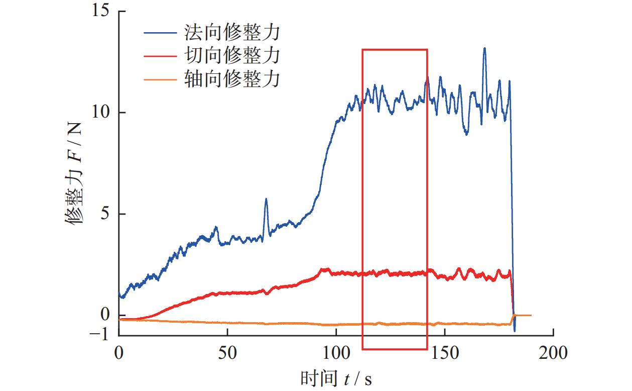
该测力仪系统一次最大记录量为200 s,达到200 s后自动保存,需手动进行下次测量,图14为错位排布修整力测量过程中Kistler测力仪配套软件Dynoware的测量数据。
从图14可以得出:x方向(轴向)的修整力始终在0值周围,表明仿真分析轴向修整力更小且接近于0的理论是正确的。取图14平稳修整时间段内的修整力数据(即图中红色框所含数据),并通过式(5)运算得到真实修整力,重新绘制得到图15与图16。
由图15与图16可知:实验所得法向修整力与切向修整力的波动相较于仿真结果更小,这是由于滚轮产品在生产加工过程中,会对其表面金刚石进行修形处理使其更锋利,其表面磨粒的出刃高度与顶点角等参数相对于仿真模型更加一致,故其修整能力更好,修整力波动更小,更加平稳。
将实验与仿真得到的修整力进行对比分析,仿真的法向与切向修整力均略大于实验所得结果,其中仿真与实验的法向修整力最大误差发生在阵列排布中,其值约为12.87%;切向修整力最大误差发生在叶序排布中,其值约为17.16%。仿真值略大的原因除包含上述磨粒形状差异较大外,仿真的修整过程为干磨,而实验为湿磨,也会对修整力产生一定影响,但是总体误差不大,仿真值与实验值总体接近,实验可以较好地验证仿真结果的可靠性。
3. 结论
通过质量分数为99.5%的Al2O3陶瓷的JH-2本构参数代替白刚玉砂轮材料性能参数,对错位、阵列和叶序3种磨粒排布滚轮修整砂轮的过程进行仿真,并设置滚轮修整实验来验证仿真结果,得到结论如下:
(1)由于磨粒形状、出刃高度等因素影响,仿真得到的修整力波动较大。由拟合线分析,阵列排布的法向与切向修整力均为最大,错位排布的次之,叶序排布的最小。即金刚石滚轮表面磨粒采用叶序方式排布,可以得到更优的修整性能,有利于延长滚轮使用寿命。
(2)设置的滚轮修整实验测得的修整力波动更小、更加稳定,其拟合值也更小,这表明对修整滚轮进行修形等处理可以使滚轮对砂轮的修整过程更加平稳,提高其修整能力。
(3)仿真与实验的法向修整力最大误差发生在阵列排布中,其值约为12.87%;切向修整力最大误差发生在叶序排布中,其值约为17.16%。仿真值与实验值总体接近,可以较好地验证错位排布滚轮的修整仿真结果,同时证明了以质量分数为99.5%的Al2O3陶瓷的JH-2本构参数代替白刚玉砂轮材料性能参数进行动力学仿真具有一定可行性。
-

图 1 轴承内圈沟道磨削用金刚石修整滚轮
Figure 1. Diamond dressing roller for trench grinding of bearing inner ring

图 5 不同排布下金刚石修整滚轮模型
Figure 5. Diamond dressing roller model under different arrangement

图 11 3种排布的金刚石滚轮模型磨粒轨迹线
Figure 11. Three kinds of arrangement of diamond roller model abrasive grains track line
表 1 滚轮与砂轮仿真模型参数
Table 1. Parameters of roller and grinding wheel simulation model
模型 外径 d1 / mm 孔径 d2 / mm 厚度 t / mm 金刚石滚轮 5 2.5 3.65 白刚玉砂轮 20 10 3.65  下载: 导出CSV
表 2 金刚石与白刚玉材料参数
Table 2. Diamond and white corundum material parameters
材料 密度 ρ /
(t·mm−3)杨氏模量 E / MPa 泊松比 v 金刚石 3.52 × 10⁻⁹ 1.05 × 10⁶ 0.1 白刚玉 3.98 × 10⁻⁹ 3.5 × 10⁵ 0.22 材料 热膨胀系数 $ \alpha $ 热导率 $ \lambda $ /
(W·m−1·K−1)比热容 c /
(mJ·t−1·K−1)金刚石 1.26 × 10⁻⁶ 2 000 4.2 × 10⁸ 白刚玉 30.145 6.0 × 10⁸
下载: 导出CSV
本构
模型密度 ρ /
(t·mm− 3)剪切模量
G / MPaA N B M C 3.7 × 10− 9 90 160 0.93 0.6 0.31 0.6 0 $ \dot{\varepsilon}_0 $ 拉伸强度
Rm / MPa$ {\sigma }_{\mathrm{i}}^{\mathrm{m}\mathrm{a}\mathrm{x}} $ $ {\sigma }_{\mathrm{f}}^{\mathrm{m}\mathrm{a}\mathrm{x}} $ HEL /
MPa$ {p}_{\mathrm{H}\mathrm{E}\mathrm{L}} $ /
MPa$ \beta $ 1 200 1.004 4 0.2 279 0 1 460.0 1 $ {K}_{1} $ $ {K}_{2} $ $ {K}_{3} $ 130950 0 0 损伤
模型$ {D}_{1} $ $ {D}_{2} $ $ {\stackrel{-}{\varepsilon }}_{\mathrm{f},\mathrm{m}\mathrm{a}\mathrm{x}}^{\mathrm{p}\mathrm{l}} $ $ {\stackrel{-}{\varepsilon }}_{\mathrm{f},\mathrm{m}\mathrm{i}\mathrm{n}}^{\mathrm{p}\mathrm{l}} $ FS IDamage 0.005 1.0 0.005 0 0.2 0
下载: 导出CSV
表 4 砂轮规格参数
Table 4. Grinding wheel specification
参数 取值 外径 d1 / mm 400 孔径 d2 / mm 203 厚度 t / mm 50 粒度 80 硬度 K
下载: 导出CSV
表 5 滚轮修整实验设计
Table 5. Roller dressing test design
阶段 滚轮转速
v1 / (r·min− 1)砂轮转速
v2 / (r·min− 1)磨削速度
v3 / (mm·min− 1)磨削量
d / mm成型修整 81 1 488 0.14 3.5 工件A 81 1 488 0.14 3.5 工件B 81 1 488 0.14 3.5 工件C 81 1 488 0.14 3.5 修整 81 1 488 0.14 0.7
下载: 导出CSV
-
[1] 李瑞昊, 石广慧, 黄辉. 磨粒有序排布曲面砂轮设计及磨削性能实验研究 [J]. 金刚石与磨料磨具工程,2021,41(4):58-63. doi: 10.13394/j.cnki.jgszz.2021.4.0009LI Ruihao, SHI Guanghui, HUANG Hui. Experimental research on design and performance of curved grinding wheels with orderly arrangement of abrasive grains [J]. Diamond & Abrasives Engineering,2021,41(4):58-63. doi: 10.13394/j.cnki.jgszz.2021.4.0009 [2] YUAN H P, GAO H, LIANG Y D. Fabrication of a new-type electroplated wheel with controlled abrasive cluster and its application in dry grinding of CFRP [J]. International Journal of Abrasive Technology,2010,3(4):299. doi: 10.1504/IJAT.2010.036963 [3] ZHANG G F, ZHANG B, DENG Z H, et al. An experimental study on a novel diamond whisker wheel [J]. CIRP Annals,2010,59(1):355-360. doi: 10.1016/j.cirp.2010.03.116 [4] KOSHY P, IWASALD A, ELBESTAWL M A. Surface generation with engineered diamond grinding wheels: Insights from simulation [J]. CIRP Annals,2003,52(1):271-274. doi: 10.1016/S0007-8506(07)60582-4 [5] OHI T. Trends and future developents for diamond CMP pad conditioners [J]. Industrial Diamond Review,2004(1):14-17,19,21. [6] 车东泽, 吕玉山, 陈天宇, 等. 用磨粒叶序排布砂轮磨削外圆生成的凹坑表面仿真 [J]. 金刚石与磨料磨具工程,2019,39(1):47-53. doi: 10.13394/j.cnki.jgszz.2019.1.0009CHE Dongze, LYU Yushan, CHEN Tianyu, et al. Simulation of the dimpled surface generated by grinding outer circle with abrasive phyllotactic arrangement wheel [J]. Diamond & Abrasives Engineering,2019,39(1):47-53. doi: 10.13394/j.cnki.jgszz.2019.1.0009 [7] 赵国伟, 吕玉山, 李雨菲, 等. 有序化砂轮磨削表面粗糙度仿真 [J]. 机械设计与制造,2018(3):223-225,229. doi: 10.3969/j.issn.1001-3997.2018.03.066ZHAO Guowei, LV Yushan, LI Yufei, et al. Simulation of the surface roughness with grinding wheel of ordered abrasive pattern [J]. Machinery Design & Manufacture,2018(3):223-225,229. doi: 10.3969/j.issn.1001-3997.2018.03.066 [8] 陈晨, 王军, 吕玉山, 等. 磨料有序化排布砂轮磨削TC4温度实验研究 [J]. 金刚石与磨料磨具工程,2015,35(5):25-28. doi: 10.13394/j.cnki.jgszz.2015.5.0006CHEN Chen, WANG Jun, LV Yushan, et al. Experimental investigation of grinding temperature when grinding TC4 with engineered grinding wheels [J]. Diamond & Abrasives Engineering,2015,35(5):25-28. doi: 10.13394/j.cnki.jgszz.2015.5.0006 [9] 李伟凡. 磨粒有序化排布超硬砂轮磨削力的研究 [D]. 沈阳: 沈阳理工大学, 2017.LI Weifan. Research on the grinding force of super-hard grinding wheel with ordering arrangement pattern [D]. Shenyang: Shenyang Ligong University, 2017. [10] 国家质量监督检验检疫总局, 中国国家标准化管理委员会. 超硬磨料 粒度检验: GB/T 6406—2016 [S]. 北京: 中国标准出版社, 2016.General Administration of Quality Supervision, Inspection and Quarantine of the People’s Republic of China, Standardization Administration of the People’s Republic of China. Superabrasive—Checking the grain size: GB/T 6406—2016 [S]. Beijing: Standards Press of China, 2016. [11] 韩程宇. 平面磨削有限元仿真及磨削建模GUI平台开发 [D]. 郑州: 郑州大学, 2019.HAN Chengyu. Surface grinding finite element simulation and grinding modeling GUI platform development [D]. Zhengzhou: Zhengzhou University, 2019. [12] ITERSON V G. Mathematische und mikroskopish-anatomische studien über blattstellungen [J]. Nature,1907,77:145-146. doi: 10.1038/077145a0 [13] SUN J, WU Y H, ZHOU P, et al. Simulation and experimental research on Si3N4 ceramic grinding based on different diamond grains [J]. Advances in Mechanical Engineering,2017,9(6): 168781401770559. doi: 10.1177/1687814017705596 [14] CRONIN D S , BUI K , KAUFMANN C , et al. Implementation and validation of the Johnson-Holmquist ceramic material model in LS-DYNA [C]//4th European LS-DYNA Users Conference. Ulm, Germany, 2003: 47-60. [15] LIU M Z, LI C H, ZHANG Y B, et al. Analysis of grinding mechanics and improved grinding force model based on randomized grain geometric characteristics [J]. Chinese Journal of Aeronautics,2023,36(7):160-193. doi: 10.1016/j.cja.2022.11.005 [16] 马少奇. 18CrNiMo7-6钢外圆磨削力及表面完整性研究 [D]. 郑州: 郑州大学, 2021.MA Shaoqi. Research on grinding force and surface integrity of 18CrNiMo7-6 steel in cylindrical grinding [D]. Zhengzhou: Zhengzhou University, 2021. -

 下载:
下载:


 点击查看大图
计量
- 文章访问数: 709
- HTML全文浏览量: 305
- PDF下载量: 12
- 被引次数: 0
 邮件订阅
邮件订阅 RSS
RSS